Week 7: Computer Controlled Machining
Wednesday 09/03/16: I had a good feedback session with Louis who explained some more electronics related issues to me. I do hope I will continue to be intrigued by this!!
In this week’s lecture, Neil explained a lot of issues regarding CNC in theory but everything needs to be put to good practice. One useful piece of information that I will definitely keep from that lecture is the fundamental difference between a drill-bit and an end-mill. The first only drills holes, the other is capable of making grooves and shapes, hence moving sideways. There are several types of endmills which differ in shapes and sizes. Most importantly there are ‘down-cut’ ones which cut in a down direction and ‘up-cut’ ones which cut upwards. There are ball-nose ones, flat-end versions, with 1, 2, 4 or more flutes — a wide variety of end-mills depending on what one wants to achieve. Some people also use router-bits on cnc machines.
Regarding our actual machining, it should definitely not be aggressive in a way that it stresses the machine or the endmill, as this could not only damage the machine, but also be the cause of accidents or fires. Eyes, ears and nose should be open to sense anything unusual like smoke.
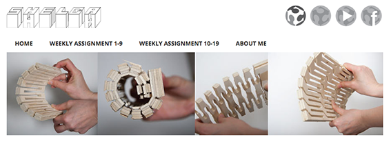
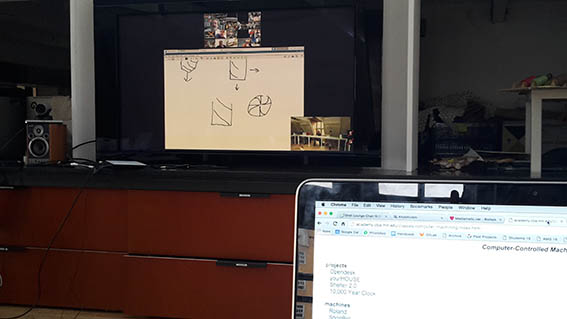
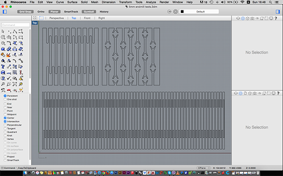
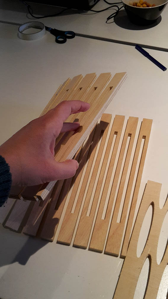
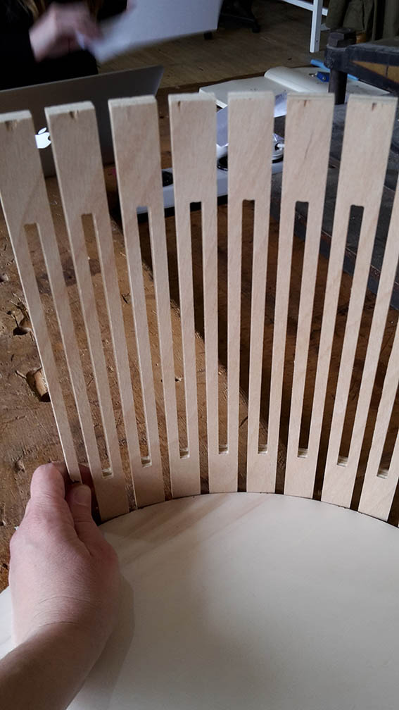
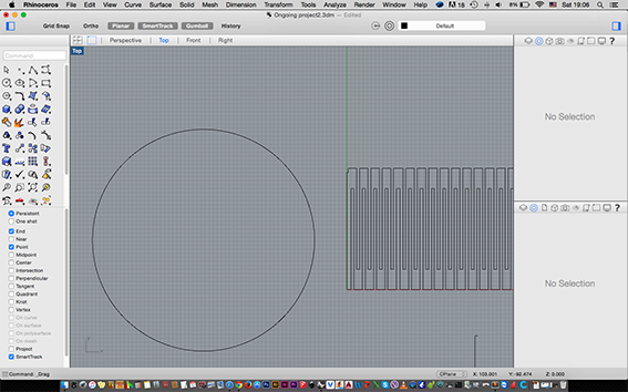
For the project I wanted to experiment with kerfing and flexures. In my training as a cabinet-maker we always needed to find very ‘stiff’ ways to produce curves with wood like bending it in layers, forming it in small blocks, steam bending and yes, sometimes manually routing out grooves all over a surface. All this seemed like very hard work and I wanted to find something more simple or even innovative. I did some research in google, but also in the FabAcademy archive from past years. I checked Helga’s website, Till’s website and this instructables page on how to make kerfs in laser cutters. From Helga I understood the most important thing: If both sides of the wood I am bending are open in an alternate pattern, then it becomes very flexible - a flexure. I then started to draw some things in Rhino that I wanted to try out and also some shapes that I thought would work. In general I tried to keep the size of the grooves smaller than the 9mm thickness of our plywood because it gave me a feeling of flexibility for the material itself.
On Thursday 10/03/16: Mickael went through the operation of the ‘ShopBot’ in great detail. One definitely needs experience on the machine to operate it safely and efficiently. There are so many parameters to take into account!
Firstly the material on which we will be cutting needs to be secured safely in place. This can happen through the use of clamps or screws. One must take care when using such fixtures so that nothing is obstructing the route of the axes.
Mickael used about 20mm of the outside border of the material to fix it with screws in place. He also made sure that this was taken into account in his drawing, which I thought was good practise. It minimizes mistakes. He explained that a ‘pocket’ is grooving shapes into the material which are lower from the surface but not cut all the way through. A ‘profile’ cut is an all through cut and the machine should be set to cut a couple of mm more than the thickness of the material. In this case, the machine should be layed out with a sacrificial layer so that the cut does not damage its bed.
The ’Partworks‘ application accepts .crv .dxf .eps .pdf .ai files. Those are also editable in the particular application which generates the path to be cut. Sometimes people face issues with .ai files which create multiple layers of vectors once opened in PartWorks. This can be solved in Rhino by typing ‘selduplicatelines’ and deleting them. Another issue is that when importing a .dxf with Rhino, the lines are not joined although they where in the original drawing. This can can also be fixed in PartWorks by selecting the lines to be joined and pressing "J".
On Friday 11/03/16: I went to the Fab Lab really early to cut, but it took me four hours to fix my files and set up the machine. One very important detail which held me back was that I had been drawing without having fully understood the path that the machine follows. Like the laser cutter, it passes over every single line (the user can of course select which paths to cut but that’s a different story). I had been drawing thinking that if I left a groove of 5mm (between two lines), it would follow… the groove - just like manually routing! After I understood this, I had to change most of my drawings and select carefully what to cut.
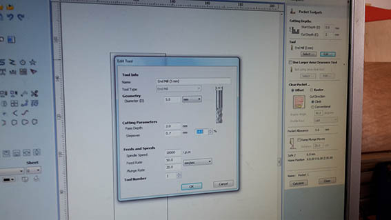
In the PartWorks application (new version called VCarve) I set the "Z" to be the the top of the material and its thickness to 9mm. I then generated a profile toolpath, the start depth to 0.0 and the cut depth to 9mm. I selected the 3mm up-cut endmill and the path to be cut on the outside. At this point I added very few tabs of 3mm x 5mm size and I calculated the toolpath. I saved it and I opened the ShopBot3 application.
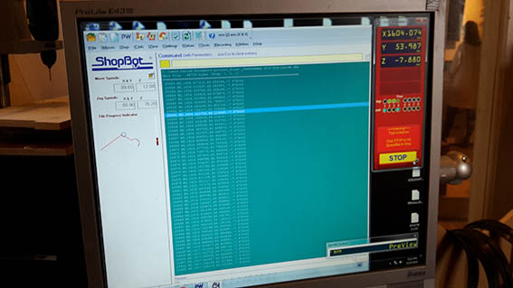
By pressing "K" the keyboard comes up and allows one to set the three axes before strarting to cut. Page up and Page Down controls the Z axis and the arrows control the X and Y. An important piece of information is that the top row in the ShopBot application is used to set the machine coordinates where the X/Y are fixed and the Z is set using the metal plate provided. The menu at the second row, is used to set the coordinates for the specific job. So I navigated to the corner of my material, where I set the ‘0’ point for X/Y and the Z.
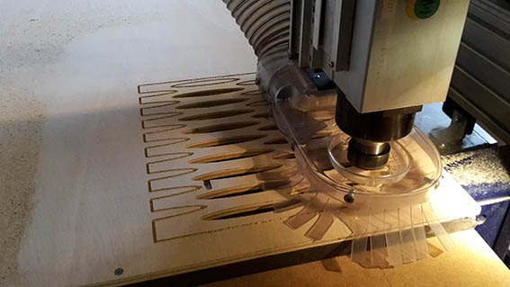
I fixed the 5mm up-cut endmill, made sure it was tight enough, turned on the extraction, put on my PPE and turned the key to start the spindle motor. I started to cut my first path at spindle speed: 18 0000, Feed Rate 60.0 and Plunge Rate 20.0.
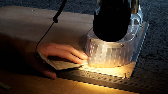
That was when I realized that I should have thought more carefully about how and where to place my tabs because each ‘eye shaped’ piece that was cut from my kerf attempts was getting trapped inside the vacuum system, very near the spinning end-mill. I got worried that it was going to break it. Mickael who was near suggested that I turn the extraction high every time one of those pieces was being released and it did seem to work, but this ended up too stressful so I stopped. I later found out that those pieces blocked the extraction of the ShopBot.
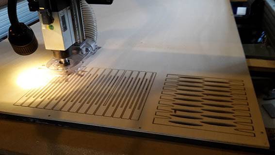
I returned to PartWorks and carefully added tabs for all pieces which were eventually going to be released. I restarted the job which finished smoothly this time. I was suprised by how long it took to cut, me only experience so far was with heavy duty industrial machines that take care of deep cuts at one go. I will experiment more with the settings during my Tuesday slot, if I have the time.
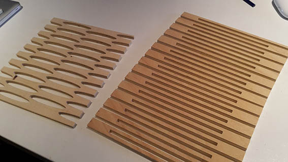
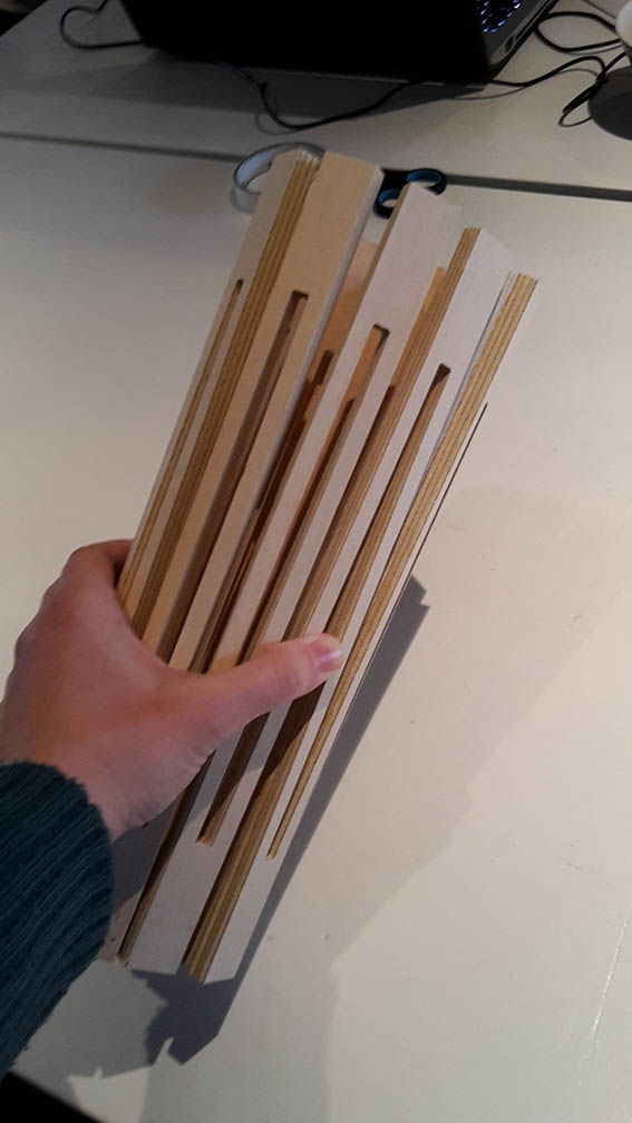
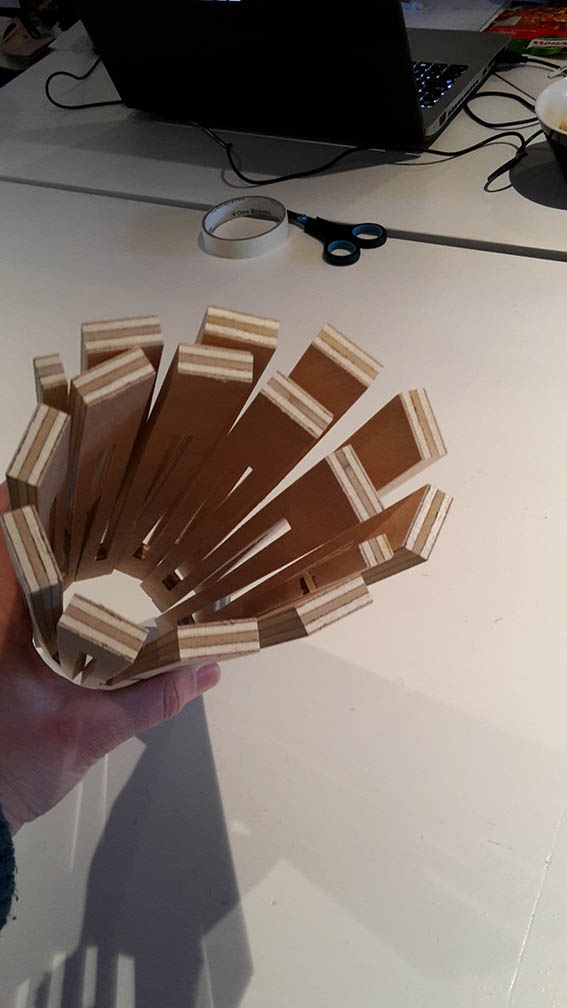
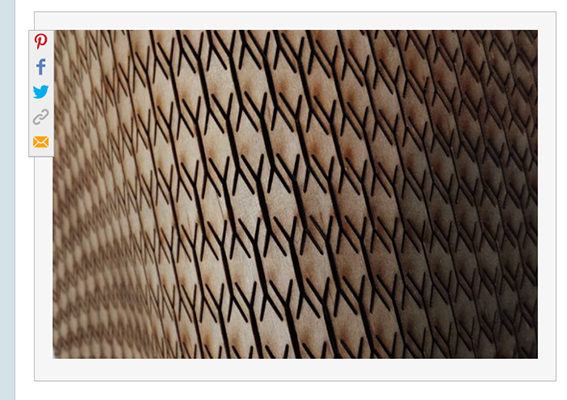
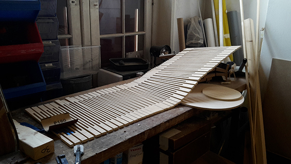
I was so excited with what I produced, although I didn’t get to cut all the trials that I had drawn. I had never before seen plywood become so flexible or even moldable but the question remained. What was I going to make and how big would it be?!
Saturday 12/03/16: Apparently Neil believes that ‘glue is a sign of failure’. Although my whole being and practise quite disagrees with this, I decided to accept the challenge for this project. In cabinet making you rely on glue and you shape the wood while always leaving room to put enough of it! I sat down to draw and calculate joints for my flexure to be fixed on round surfaces. Still a little unsure of what I am making, jumping back and forth between ideas of what this assignment could become.
On Sunday 13/03/16: I continued to design in Rhino which is becoming more familiar to me. I still have a long way to go, especially with parametric design, but I am really beginning to love it!
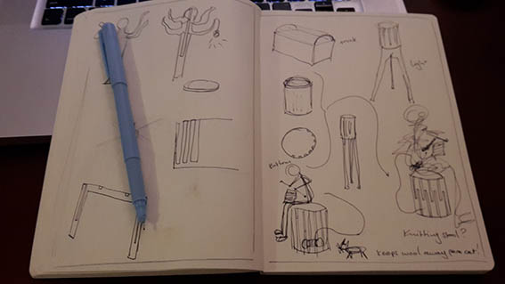
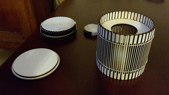
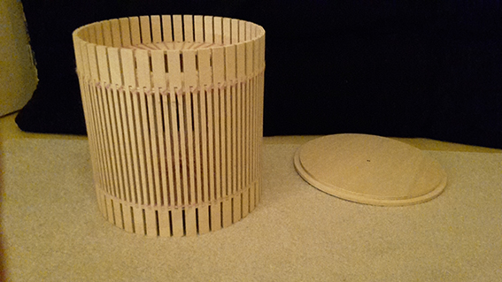
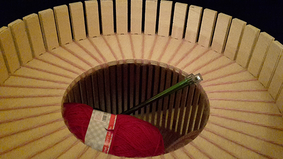
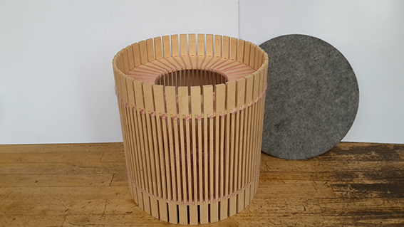
I tried to predict how the joints would work as well as how the structure would hold. I also played with shapes for little children toys. In the end, I am planning to make a small cylindrical stool, but this is challenging because I need to take into account the weight of the person sitting on it. More specifically I am modellling a ‘knitting stool’. I gave it that name because it can act as a container for wool and knitting needles. It can also allow the yearn that one is knitting with to be fed through the gaps, therefore keeping it out of the reach of… cats who usually mess up the cord!! (Apparently they sometimes end up at the VET, too!)
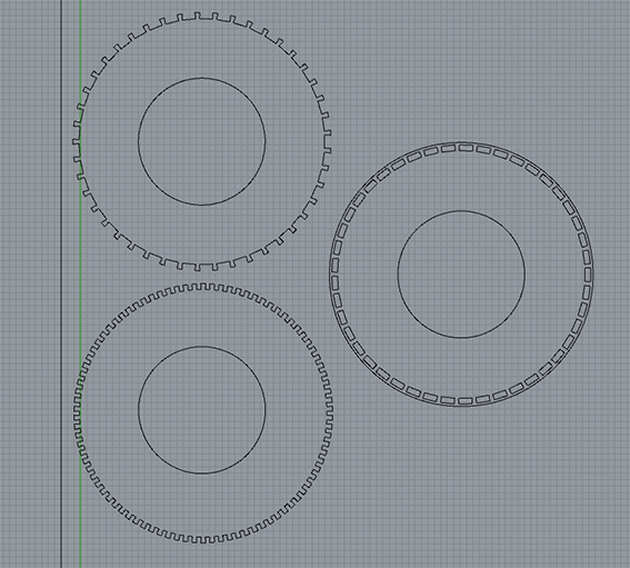
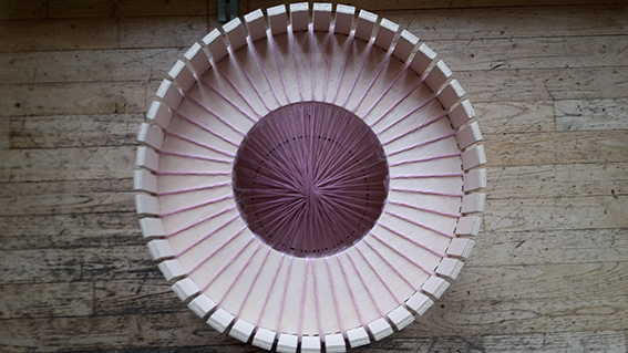
I designed three kinds of joints. In one occasion the flexible plywood would be fixed around a circular base from its outside edges. On the second it would be held by the circular base from its the middle section and on the third I allowed for a lip around the joints of the circular base.
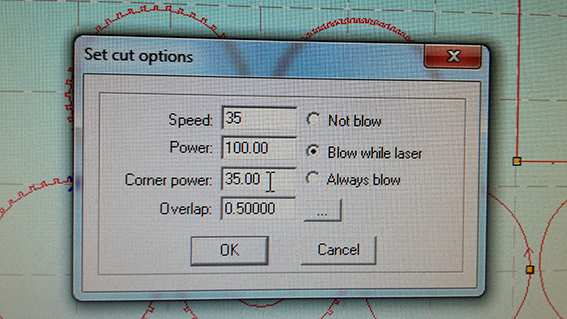
On Monday 14/03/16 I reserved the laser to make the tests. Upon arrival to the Fab Lab, I spoke with Mikael who pointed out that 9mm would be hard to cut in the laser-cutter and that it would be best to make a scaled model. In the end I decided to go ahead with cutting samples of some of the joints, even though I knew there would be a small difference in the final outcome. I used 4mm plywood, a speed of 35 and a 100 power, which made my cut a little uneven.
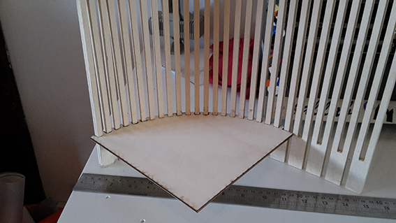
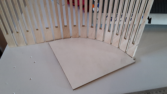
I was mostly satisfied with the results. The small ‘dovetail’ joints that I designed and cut on the laser-cutter seemed to work on the flexure that I already had cut on the CNC, while at the same time giving it some more tension, so I expected no suprises for the next day. Mickael also suggested that I cut a scaled model of the stool so I went ahead with it. It is always best to visualise something in 3d before continuing to model on the computer. I most specifically wanted to make sure that I had enough joints for the whole length and vice versa!
The scaled model worked quite well. Although it needed to be held in place with rubber bands, I thought that wouldn't be an issue on the bigger stool. In fact I believed that the joints would be just snug on the CNC version and that they would hold the stool in place tightly. I made a selection of which joints I thought fitted better and I attended to designing some details on how the flexure would close evenly on itself. I arranged my drawing and exported to dxf. The ‘knitting stool’ was ready for cutting on Tuesday!
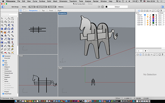
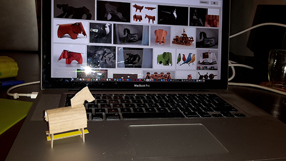
Since I was quite confident with my tests I proceeded to have some fun and design a wooden horse. I was hoping that I would be able to cut two projects, if I had the time.
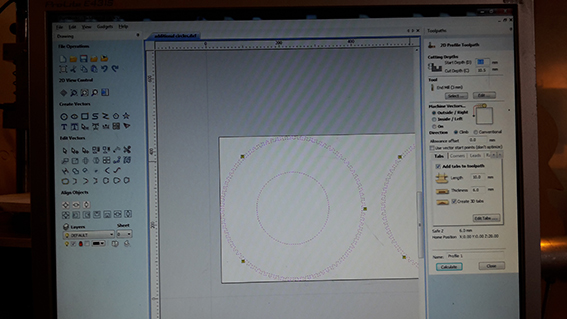
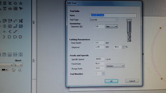
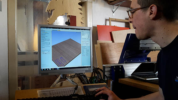
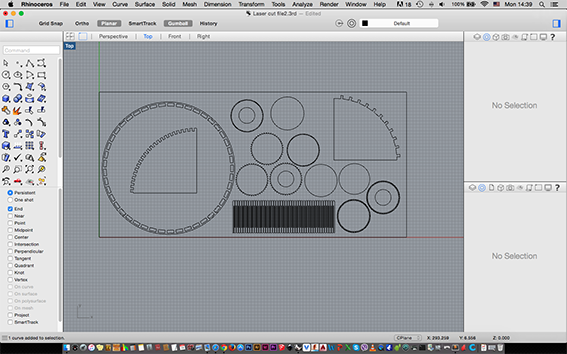
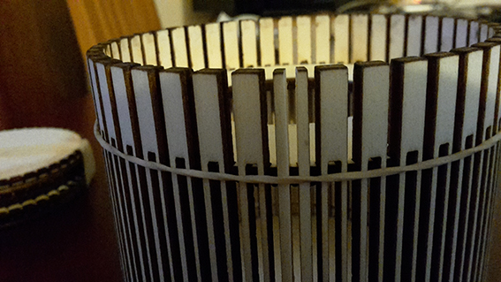
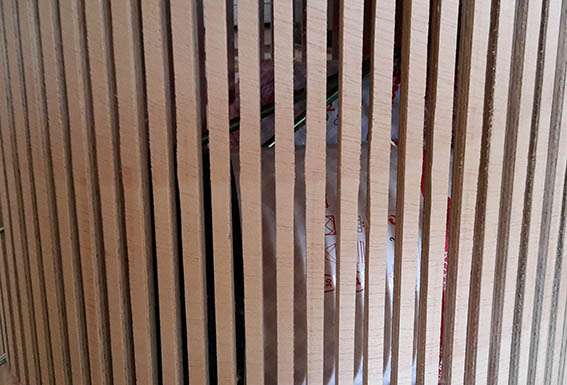
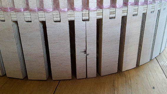
Tuesday 15/03/16 While I was waiting for my turn to cut I realized that cutting two projects was over-ambitious while others had to also make their cuts so I proceeded to re-arrange my drawing to only cut the knitting stool. I created three cutting paths. One for outside cutting, one for inside and one for holes. I am becoming more comfortable with the use of both PartWorks and the ShopBot application. I used the settings in the photo above but I thought that I had this time chosen a down-cut endmill. As it turns out, I had used a down-cut endmill on Friday and an up-cut today.
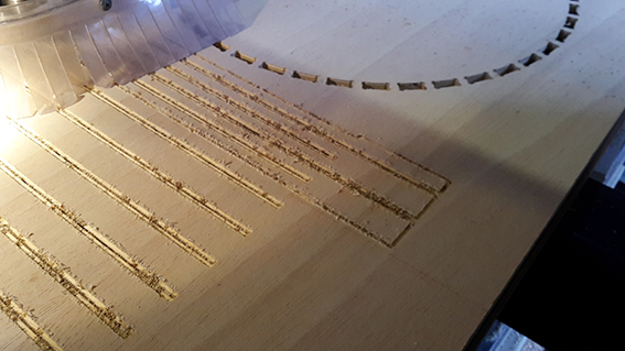
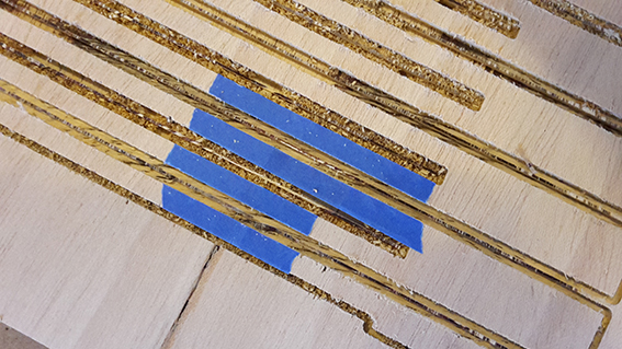
This can be clearly seen in the images, where the wood is chipping at the surface. I was also unfortunate enough (and a little careless in all my stress) to have a plywood flaw right on where I was cutting my 1260mm flexure. This caused further chipping and I had to pause my cut to tape down those areas, in an attempt to prevent further damage. I believe this trick worked.
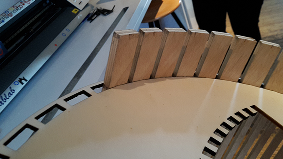
While I was milling, it started to become clear that the joints on my circular pieces were too wide for the narrow grooves. I had designed the small dovetail joints with an opening of 6mm while the section that was going inside them was 7mm. The plywood simply was not going to have the flexibility I thought it would from my laser tests. I should have used my time more wisely and designed accurate joint tests to cut on the CNC instead of just trying on the laser-cutter. Everyone’s tests were delivering the same result, however. Milling the exact width of the joint on both sides gave a fit. My assumption was that 1mm would only make it slightly tighter. I acted quickly and produced another set of joints which was able to cut. I really appreciate the active help and understanding of my colleagues Marije, Sander and Jacopo in this matter. The new joints were 7mm as was the width of the part that was going inside it, but it is not a tight fit.
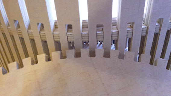
The tabs are becoming a big chapter. I added them on the perimeter of my piece on every single section that was going to be released, but I should have added more between the grooves. On the finished piece it is visible that they were not kept securely in place during milling as the cuts are not completely straight and sharp. So even more care next time!
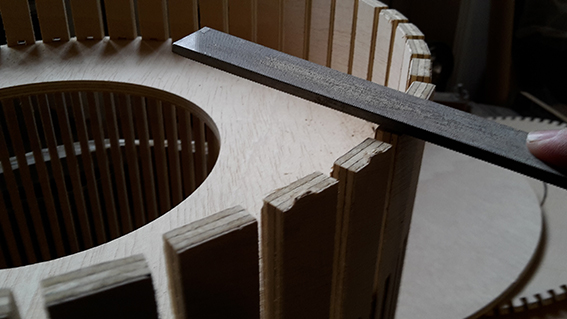
Then it was the turn of sanding and filing the parts, especially where all the tabs where. I had added one on both sides of the grooves because that was the only way of holding it in securely in place. I slowly rolled the flexure around both circular joint modules, slowly securing them in place. By then I was a little disappointed because it was not holding together on it’s own. I was considering adhesives! Glue or no glue the fact remained that it needed something to hold it together. I succeded with the flexure, failed with the joints… I need to add an engineering twist to my design thinking!
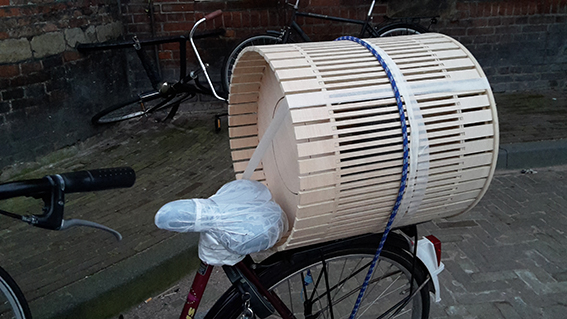
I taped it together so I could carry it home for the finishing touches. I fixed it on the bike and had an interesting ride home.
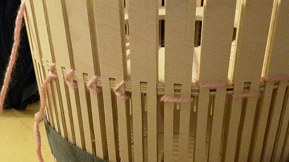
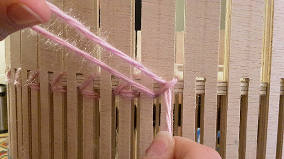
In the end I decided to follow a more ‘organic’ approach and utilized the wool yarn that is supposed to be kept in the stool to hold it together. I tangled it in different ways with the goal of pressing the joints together as tightly as possible. Glue may be a sign of failure but wool is cool!
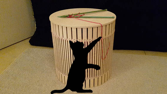
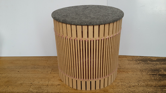
I am happy that I attempted something that was not a ‘safe bet’ for me. For most of the week what troubled me was the approach that I should take. Make something that I feel comfortable with and be sure of the outcome, or experiment with new territories? I am glad that I took the plunge and I am quite happy with the result. There is always room for improvement, especially for a project that lasted only one week, but most of my goals were accomplished. I am comfortable with the ShopBot, I made a flexure, I have a solid and tidy final object. Now I just need to lure that cat in for an actual photo…
Knitting Stool Drawing - File Computer Controlled Machining Lecture Global Review - Knitting Stool Back to Weekly Assignments Home